Pump-attuned valves improve energy efficiency
By Uwe Herberger-Rosin, KSB Aktiengesellschaft

Fig.1: BOA RVK wafer-type lift check valve
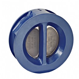
Fig.2: SERIE 2000 wafer-type dual plate check valve
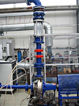
Fig.3: Test set-up for examining the behaviour of check valves in combination with variable speed pumps
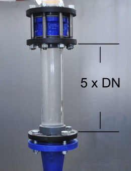
Fig.4: A SERIE 2000 dual plate check valve with flow stabilisation section
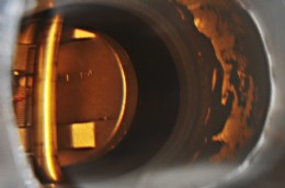
Fig.5: Looking inside a SERIE 2000 check valve
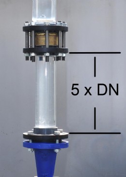
Fig.6: A BOA-RVK lift check valve with flow stabilisation section
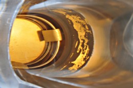
Fig.7: Looking inside a BOA-RVK lift check valve
Check (or non-return) valves are needed when a pump is stopped and the liquid column acting on the discharge nozzle or the pressure generated by other pumps operating in parallel could cause the impeller to reverse direction. Sensitive components like unidirectional mechanical seals could sustain damage as a result. If an appropriate valve is installed, any reversal of flow will close it, thus providing reliable protection against reverse flow.
Often, however, lift check valves (Fig. 1) and dual plate check valves (Fig.2) are installed without first having examined the prevailing flow conditions and resultant energy losses.
Frequently, the pump is the major point of focus at the time of installation, while the check valve is selected en passant, so to speak. Depending on the equipment configuration, this can cause serious wear and tear on the valve or even keep the system from achieving good performance.
The advent of speed control systems, though, has changed the situation for check valves. While pumps used to be either “on at full load” or “off”, many units are now operating at reduced speed in the part-load range.
When lift check valves are used, low flow velocities can cause constant “opening and closing”, because, unlike dual plate check valves, they are unable to reliably maintain a partly open position. Consequently, they might use up their entire service life in terms of opening/closing cycles within a few weeks. High volume flows can also cause problems due to high flow velocities in the narrow gaps at the disc/seat interface. This can lead to such pronounced wear and vibrations as to cause the eventual failure of the valve. Indeed, resonant vibrations might even cause damage to the pump itself.
Frequently, the connecting piece between the pump and the check valve is too short. As a rule of thumb, the valve should be situated at least the equivalent of five nominal diameters away from the pump – a length referred to as the flow stabilisation distance.
In a study conducted by KSB, more than 30 percent of all check valves were found to have been incorrectly installed, poorly selected, or undersized. There were even cases in which the installed check valve consumed nearly half of the head generated by the pump! Considering the huge number of check valves now in service in industry, there is an equally huge potential for cutting costs.
Tests document high savings potentials
In order to closely analyse the opening behaviour of check valves KSB has subjected its SERIE 2000 wafer type dual plate check valve to extensive tests on a purposebuilt test rig (Fig.3). The basic goal was to examine which kind of check valve – wafer-type dual plate check valve or wafer-type lift check valve – is most suitable for which kind of application. Both types were therefore tested in diverse situations.
In the first test set-up, the technicians installed a lift check valve without a flow stabilisation section. The results agreed with practical field data. At minimal volume flow, the opening behaviour was unstable, and the valve began to chatter. At maximum flow, the spring vibrated strongly due to the high velocity of flow through the valve. Even the subsequent installation of a flow stabilisation section failed to improve that behaviour.
In the second set-up, the technicians installed a dual plate check valve with, and then again, without a flow stabilisation section (Fig.4). This time, the opening behaviour observed remained stable, even with the valve in a partially open position, and there was no chattering as in the case of the lift check valve (Fig.5). Any unsteady behaviour of the dual plate valve discs was remedied by installing a flow stabilisation section.
Under low flow conditions, the lift check valve remained very unsteady despite installation of a flow stabilisation section (Figs. 6 and 7). Consequently, such valves should only be installed in cases where space constraints leave no room for any other choice, because its unstable opening behaviour can, under certain circumstances, result in a very high rate of wear. Nor is this kind of valve inherently suitable for use with a frequency inverter. This is also evidenced by a comparison of head losses calculated for both types of valve.
The individual loss coefficient, ζ, of a wafer-type lift check valve is approximately 4.5. With a dual plate check valve, the situation is intrinsically more favourable, because there is no change in the direction of flow in the valve, so its ζ value, at 0.4, is much better.
This can also be demonstrated by way of the head loss, Hv, as calculated according to the following equation. DN 200 mm pipes were selected on the basis of assumed flow velocities of v = 1 - 1.5 m/s on the suction side and v = 2 - 2.5 m/s on the discharge side. Applying these data, the equation yields 1 m as the head loss attributable to the lift check valve. The same equation yields a head loss of just 0.08 m for dual plate check valve. Depending on the application in question, this could mean that a smaller pump could be installed.
Hv = ζ Hv = ζ V2 / 2g = ζ V2 / 2g
To ensure stable, vibration-free behaviour of the closing elements, though, even dual plate check valves need a flow stabilisation section measuring about 5 x DN. This helps ensure smooth and energy-efficient pump operation under any set of load conditions.
Conclusions drawn It pays off to take a holistic view of the valve, the pump and the frequency inverter as a system. The cost of installing a new valve redeems itself very quickly. Of course, optimal matching of pump and valve is not the only way to reduce energy expenditure. No matter which measures are taken, though, the decisive factor is to ensure that the system is designed to match the operating point.
KSB
Tel: 00 (44) 1509 231872
www.ksb.com
Published: 2nd December 2012
Rachel Wormald, Managing Director at YPS Valves Ltd and Elizabeth Waterman, ...
Are you looking for industry-leading, brand independent valve and actuator ...
As can be seen from the photograph, clearly the resident birds at Bartlett ...
Howco Group has unveiled its latest £1million investment, with the ...
In 2024, Allvalves is poised for an exciting year of growth and expansion, ...
GMM Pfaudler Engineered Plastics & Gaskets are delighted to bring the ...
In the ever-evolving valve industry, GMM Pfaudler stands out for its ...
SAMSON Controls Ltd – part of the SAMSON group - a renowned leader in ...


