
Advanced Valve Solutionssteam cooled attemporator
Innovative Solution to Thermal Shock Problems in Power Generation

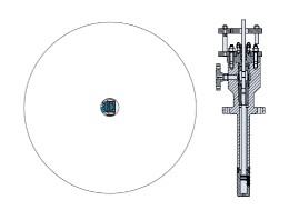

HORA standard cooler with two additional stages, single forged body and multi nozzle head.

HRSG schematic with the installed coolers, cooling steam and preheated injection water.
Two shift operation power plants
Power stations that were originally designed for base load applications are now increasingly being asked to operate on a two shift, stop start regime, more commonly known as dual shifting. The multiple start/ stops that these stations are now experiencing, has the potential to increase of operational issues due to the to the constantly changing process parameters.
For example dual shift stations will experience additional thermal stress in the headers, drums, high temperature piping, valves plus the auxiliary equipment leading to additional wear and tear of their systems and result in early failure of component parts. The consequences cannot be ignored, if the plant is not operated correctly or more importantly modified properly to handle these changes the lifetime of the components within the plant will decrease enormously.
The changing operational requirements of the plant, require the steam attemporators, de-superheater valves, drains, feed water control valves, main steam isolation valves and the turbine quick closing valves are reviewed. These critical pieces of equipment have to be specifically designed to take the new dual shifting process requirements into consideration, this done operational performance of the plant can be improved and wear and tear of systems and components can be controlled and significantly reduced.
Consequently as these pieces of equipment have been specifically designed for the new operating conditions of the station they are no longer a limiting factor to the start up time of the plant.
The following paper highlights some of the more common issues found in duel shifting power stations with special regards to steam control.
Steam cooling, the Theory
Steam cooling is the opposite process of super heating, and is in fact the controlled destruction of energy, however this function is crucial in steam boilers and other process installations.
As the cooling water is brought into the superheated steam, which will immediately reach boiling point and will to evaporate into a fine mist. The energy needed to do so is taken from the steam around the water and the temperature of the steam is effectively reduced. The graph below details two lines, with the blue line indicating the steam temperature, while the red line represents the water temperature.
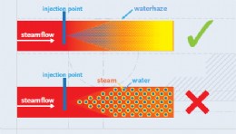
1. The droplet size of the injected water should be maintained, as small as possible. If the water droplets, brought into the steam process line, are as small as possible, the combined droplets form an enormous heat exchanging surface. Therefore quick cooling will take place, whereby the potential for thermal shock is significantly reduced. Several solutions to create small droplets can be defined through correct atomisation control, and as highlighted.
Furthermore, the temperature of the cooling water should be as high as possible, as this helps in the evaporation process
2. The cooling water has to be injected into a turbulent steam flow, with a minimum velocity of 8 m/sec.
The turbulence will assist the droplets in evaporating. It agitates the droplets and prevents them from staying in a straight flow line.
3. The cooling water has to be injected throughout the whole flow, so all the steam can be cooled to the pre-set or desired temperature.
Care should be taken to avoid injecting only into the centre of the process medium, which could give the effect of a two phase flow. Unequal distribution of droplets by means of too narrower pray pattern could lead to a two phase flow condition known as stratification. This effect has been known to give some spurious temperature readings downstream of the device ultimately leading to poor temperature control. If you should have temperature problems please contact us.
4. Sufficient superheated temperature
Steam cooling cannot be done till approx. 8 deg C above saturation, due to the influence of the wall temperature.
If the 4 points below are fulfilled good steam cooling can take place
steamflow
injection point
waterhaze
steam water
Until now we discussed small droplets, representing a huge surface area which will assist to make evaporation as quickly possible.
How to create small droplets? This requires energy.
1. By means of a pressure drop
If water is pushed through a fixed orifice, its velocity will create small water droplets. A nozzle is a piece of equipment that optimizes the creation of fine droplets. Nozzles can be used as single injection points or can be brought together in a multi nozzle injection cooler. Venturi cooler with a single nozzle injection. The venturi increases the velocity and the turbulence. The cooling water flow is controlled by a separate control valve. A single point nozzle injection. The cooling water flow is controlled by a separate control valve.
2. Steam atomizing using the velocity of critical expanding steam.
The velocity of critical expanding steam can be used to atomize cooling water. This method is good at creating fine droplets over the full rangeability. Steam is brought into the outer ring, feeding into a number of bores. Critical expansion will take place creating high velocity steam. From the inside of the core, cooling water is injected through small bores into the high velocity steam. The water flow is controlled by a separate control valve The cooling water is atomized and will cool the steam down stream the cooler.
From Base load operation to start up
Installations, running on base load do have a fairly constant set of process conditions. The implication is that the coolers are also running on a similar constant load condition. A basic old style cooler designed for these applications will work. Old style coolers are based on a perforated tube with a simple array of small holes. As long as the pressure drop is high enough and there is enough turbulence from the steam flow the cooler can work satisfactory. However if an installation is starting and stopping every day the cooling requirements are far more onerous, For a start the required valve rangeability is very high. Starting from an absolute minimum up to the maximum process conditions, through all these conditions the cooling water has to be sprayed properly The requirements can be fulfilled by different types of coolers. The steam assisted atomizing units are performing well in these circumstances. However single nozzle coolers are limited in their rangeability in these instances. A cooler with a number of nozzles will give a correct result. For this design a piston with piston rings is opening the nozzles one by one. At a minimum flow only one small nozzle can atomize really small mass flows, at maximum capacity all nozzles, up to 24 pieces can spray an impressive amount of cooling water. In all cases the water droplet size remains at its optimal size.
Multi nozzle coolers
The multi nozzle cooler is based on the use of a set of nozzles, to be opened one by one. When pushing down the plug will open the different nozzles. A continuous and fine cooling spray, based on the correct pressure drop is the result.
There are more design features to be recognized in this design:
First of all, the valve body, located in the mass flow will create bending forces. HORA is building the body of the valve in one piece, forged in several material qualities, such as F1, F11, F22 and P91.
The second advantage is formed by the location of the seat: outside the hot part of the cooler, the seat will seal the injection water.
In case the cooling water pressure is very high it is possible to install additional pressure reducing stages. This feature always maintains an optimum pressure drop over the nozzle. A number of these coolers have been fitted to a coal fired power station in The Netherlands, The coolers, fed from the main feed water pump at 220 barg are cooling the hot reheat at 50 barg. The 170 bar pressure drop is handled by three control stages and the nozzle head. The coolers are performing very well.
The cooled cooler
There are applications for steam coolers in very complex situations. If a cooler is not working continuously and only has to function occasionally. This can occur for example during start up and shut down or in case of an emergency to protect the main steam lines. In this instance the nozzle section will become very hot. The moment the cooler is required to start, thermal shock will occur and the cooler will be permanently damaged.
With the development of the cooled cooler these applications can be easily solved. Based on a reversed heating jacket or cooling jacket. Saturated steam, extracted before the super heaters is used to keep the cooler at a more acceptable temperature. The cooling steam, is later mixed with the superheated steam on leaving the cooling jacket.
The cooled cooler:
Number of possible cycles. > 100,000
Technical life expectancy 25 years
Advanced Valve Solutions UK Ltd
Tel: +44 1372 360046
www.avsnl.com
Published: 5th December 2013

Rachel Wormald, Managing Director at YPS Valves Ltd and Elizabeth Waterman, ...


Are you looking for industry-leading, brand independent valve and actuator ...
As can be seen from the photograph, clearly the resident birds at Bartlett ...
Howco Group has unveiled its latest £1million investment, with the ...
In 2024, Allvalves is poised for an exciting year of growth and expansion, ...
GMM Pfaudler Engineered Plastics & Gaskets are delighted to bring the ...
In the ever-evolving valve industry, GMM Pfaudler stands out for its ...
SAMSON Controls Ltd – part of the SAMSON group - a renowned leader in ...